Deep Ocean Seismic Research
Hellenic Arc · Peloponnese · Greece
Marine Seismology
Deep-ocean seismic activity. Photographs taken during ocean trials on the Hellenic Arc subduction zone.
At the heart of the work is a yellow free-fall penetrator designed to bury itself 10s of metres into the seabed, record seismic activity, and transmit this back to the surface accoustically.
2+ tonnes
Instrument mass
100+ mph
Free-fall velocity
3 km+
Operational depth in deep-ocean conditions
20° / 120 W
Directional underwater communication system
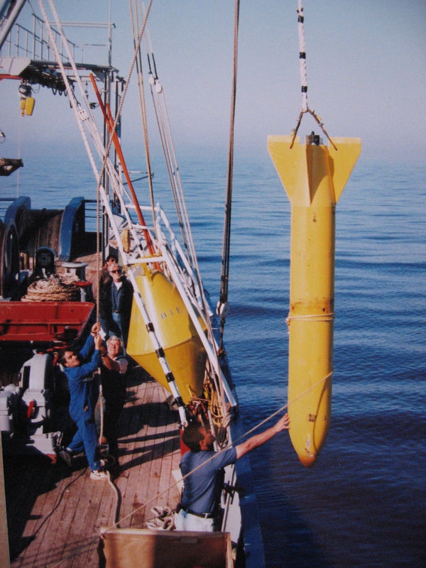
Deployment moment
The free fall device was released from a neutrino research vessel and allowed to descend at high speed before embedding itself deep into the seabed.
The Research Story
The trials combined marine engineering, geophysics, and underwater telemetry in one demanding operational environment. The result was a method for placing a seismic sensor deep into marine sediment without conventional drilling.
Project summary
- Deep-ocean seismic research at depths exceeding 3 km.
- Field trials conducted on the Hellenic Arc subduction zone, off the Peloponnese.
- Free-fall penetrator deployed from a neutrino research vessel.
- Embedded operation with subsea-to-surface acoustic data transmission.
From sea surface to buried instrument
The penetrator was designed for free fall through the water column before striking and burying itself in the seabed. The reported burial depth was equivalent to the height of Niagara Falls, turning a dramatic descent into a stable measurement platform embedded within the sediment.
Built for deep-ocean conditions
The work focused on seismic activity at ocean depths exceeding 3 kilometres, where deployment, recovery planning, and signal transmission all become more technically demanding than in shallow-water trials.
Purpose of the system
Once embedded, the instrument measured seismic activity and transmitted its data back to the surface, allowing remote observation of signals from a deep and geologically active marine setting.
Engineering & Telemetry
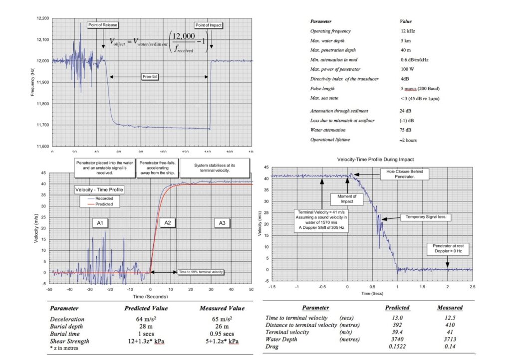
The attached technical figures add context to the field photographs by showing impact behaviour, burial estimates, and subsystem layout. Together they explain how the penetrator moved from release, to embedment, to acoustic transmission.
Impact & burial
Technical plots indicate the transition from release to terminal velocity, followed by rapid deceleration on impact and final rest within the sediment. This behaviour underpinned the instrument’s ability to operate as a buried seismic sensor rather than a drifting water-column device.
- High-speed free fall provided the momentum needed for seabed penetration.
- Embedment created mechanical coupling with the sediment for seismic sensing.
Directional underwater link
A custom-built acoustic communication system used a 20-degree beam and 120 watts of power to send information back to the surface. That directional design helped concentrate energy for transmission in a challenging underwater environment.
- Custom telemetry connected the buried instrument with surface operations.
- The communications package formed part of the wider experimental design, not an afterthought.
Integrated subsystems
The instrument package combined sensing, electronics, batteries, amplification, and housing within one penetrator body. The annotated imagery shows a compact research system engineered for deep deployment rather than a simple drop weight.
- Mechanical design and sensing function were tightly linked.
- Operational success depended on both impact physics and onboard electronics.
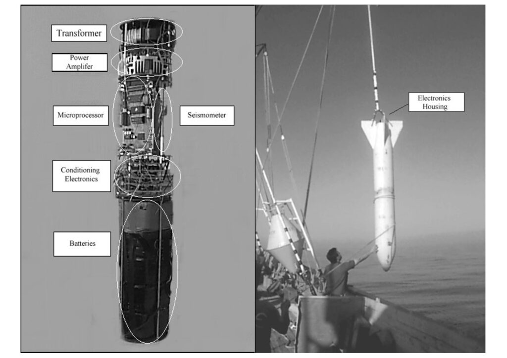
Annotated imagery showing the internal system arrangement and an external deployment view.